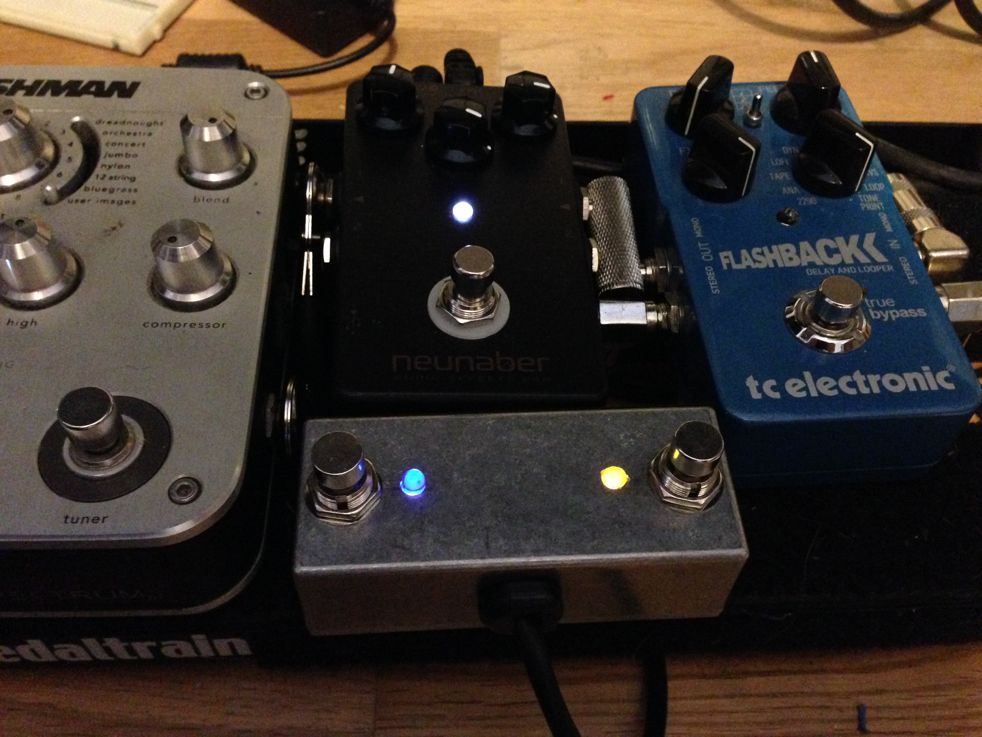
I recently purchased a Neunaber Slate pedal for the amazing Wet Reverb effect. However all the v2 of their stereo pedal range support up to 4 effects, with 2 presets per effect. They make an external controller to control this, but its a little too big for my Pedal Train Mini. You can see a demo in the video below:
Update July 2015:
Anders Jepsen has provided some updated information if you have issues with switch:
avaliable to download here.
Update March 2016:
For those of you that have visited before, I now have a new improved circuit that just uses a SPST which means you can use soft touch switches :) It’s also much more stable when switch and shouldn’t have the random/glitchy issues that some have experienced.
Update July 2017:
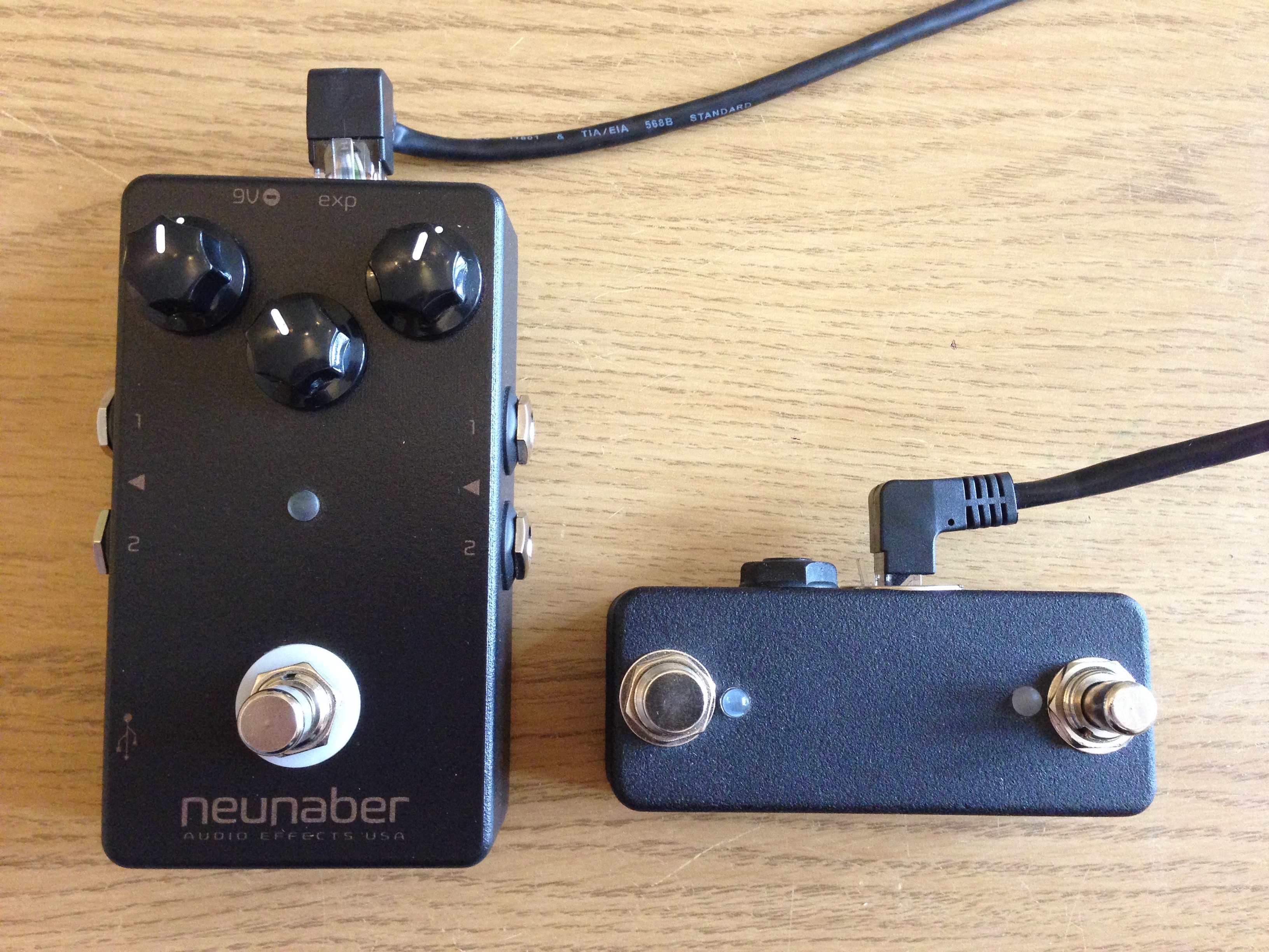
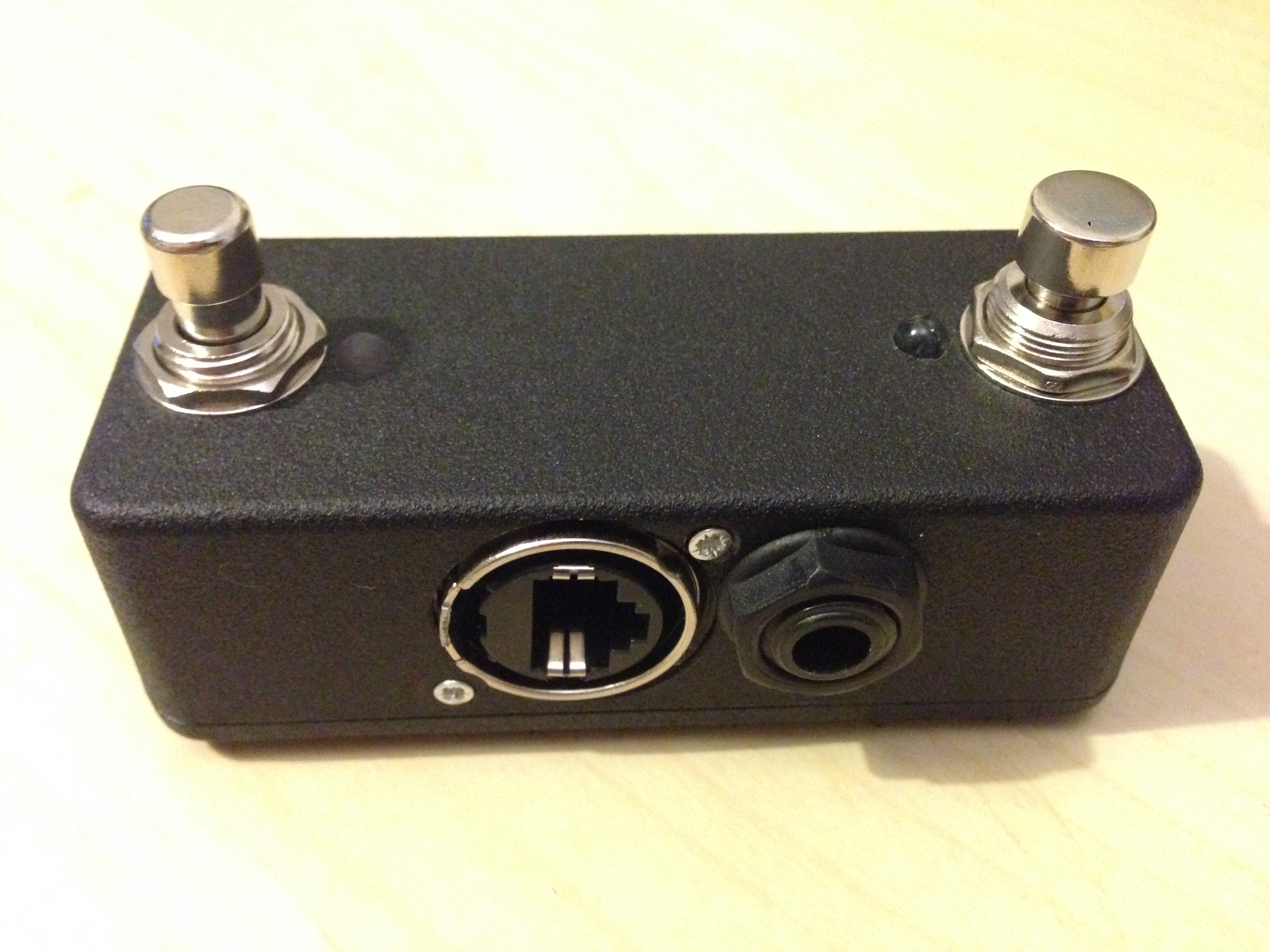
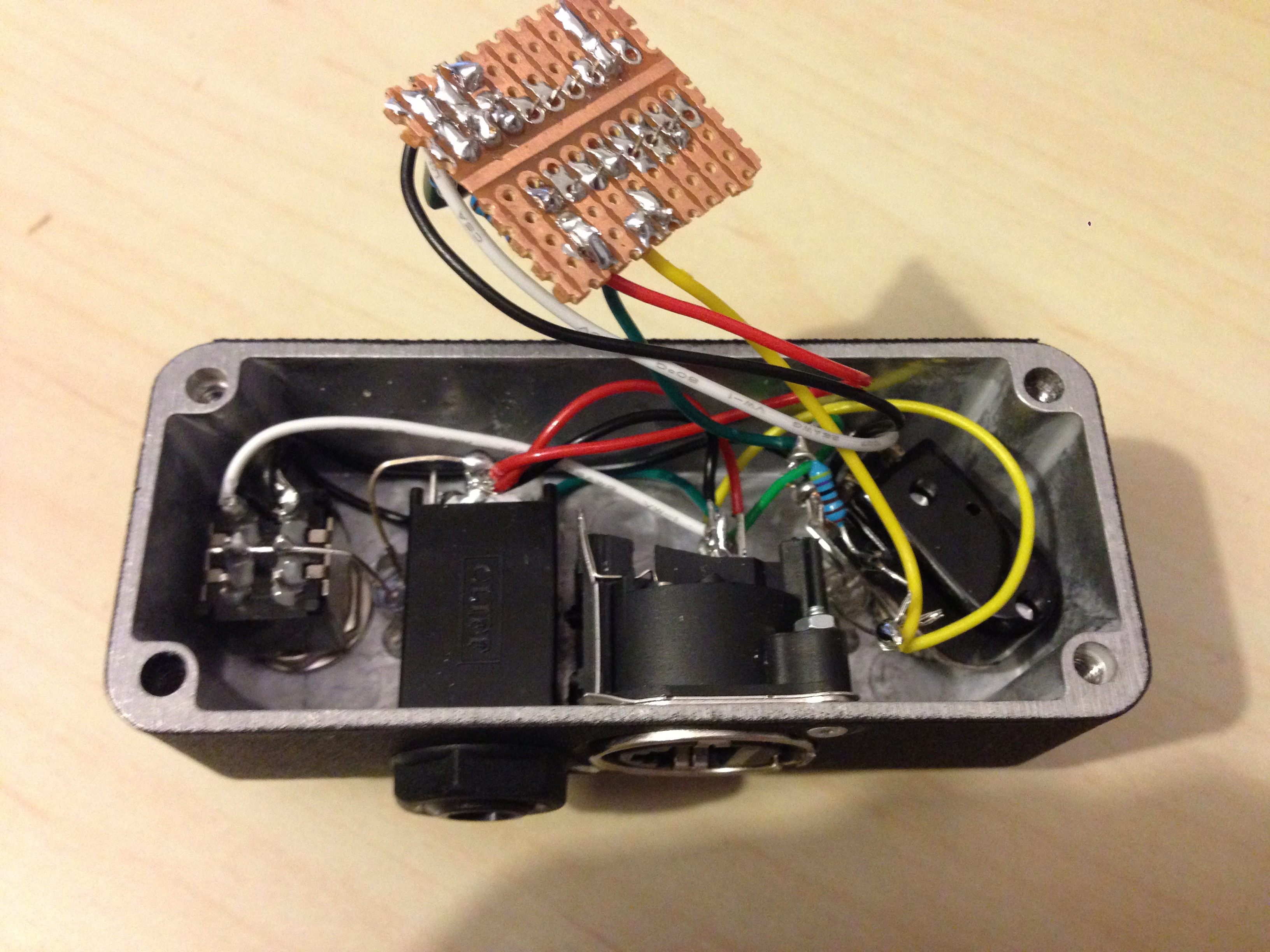
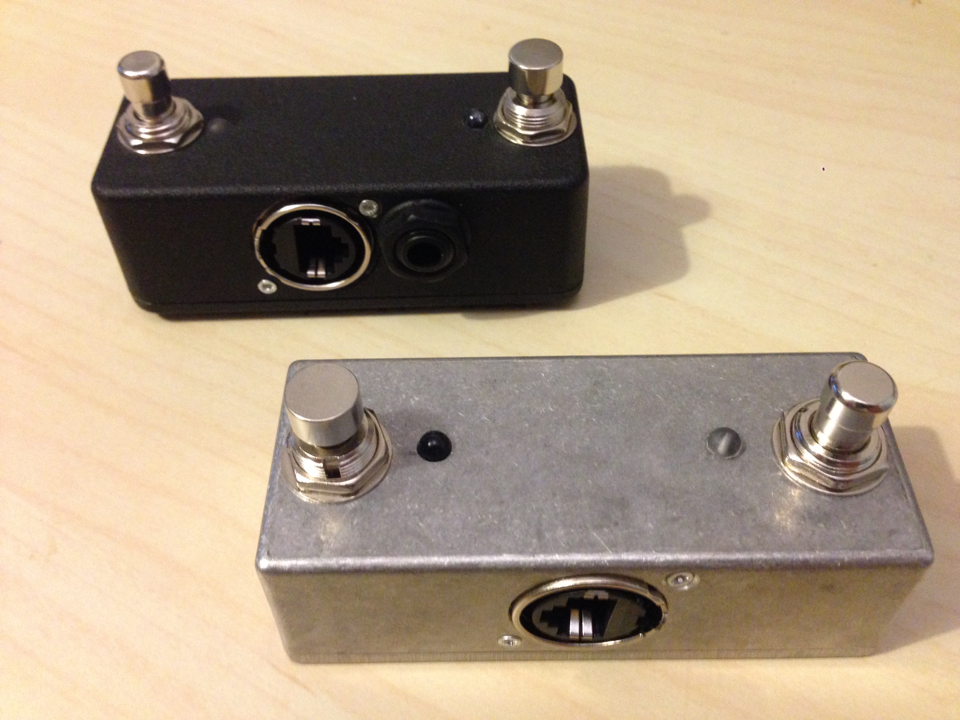
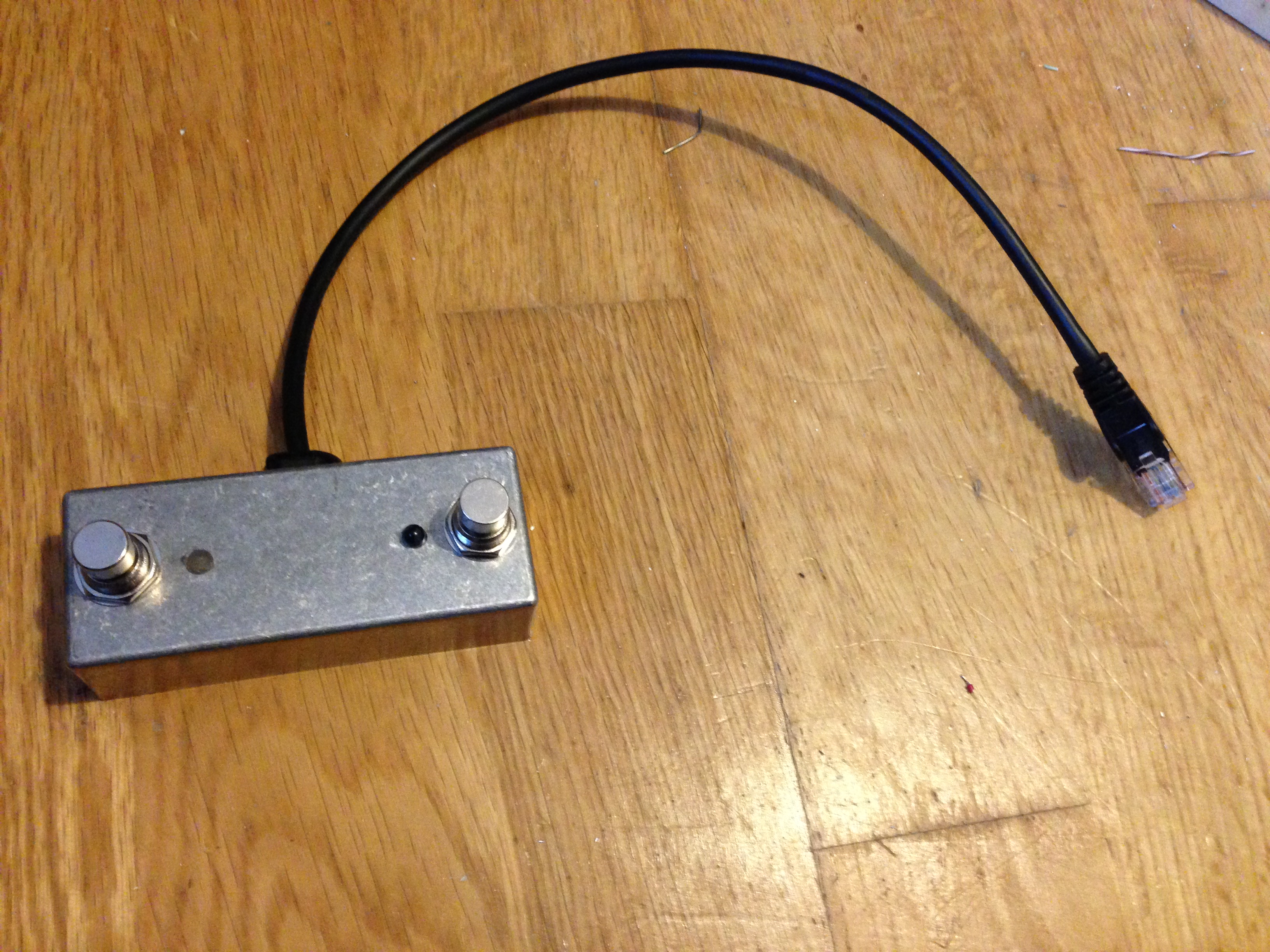
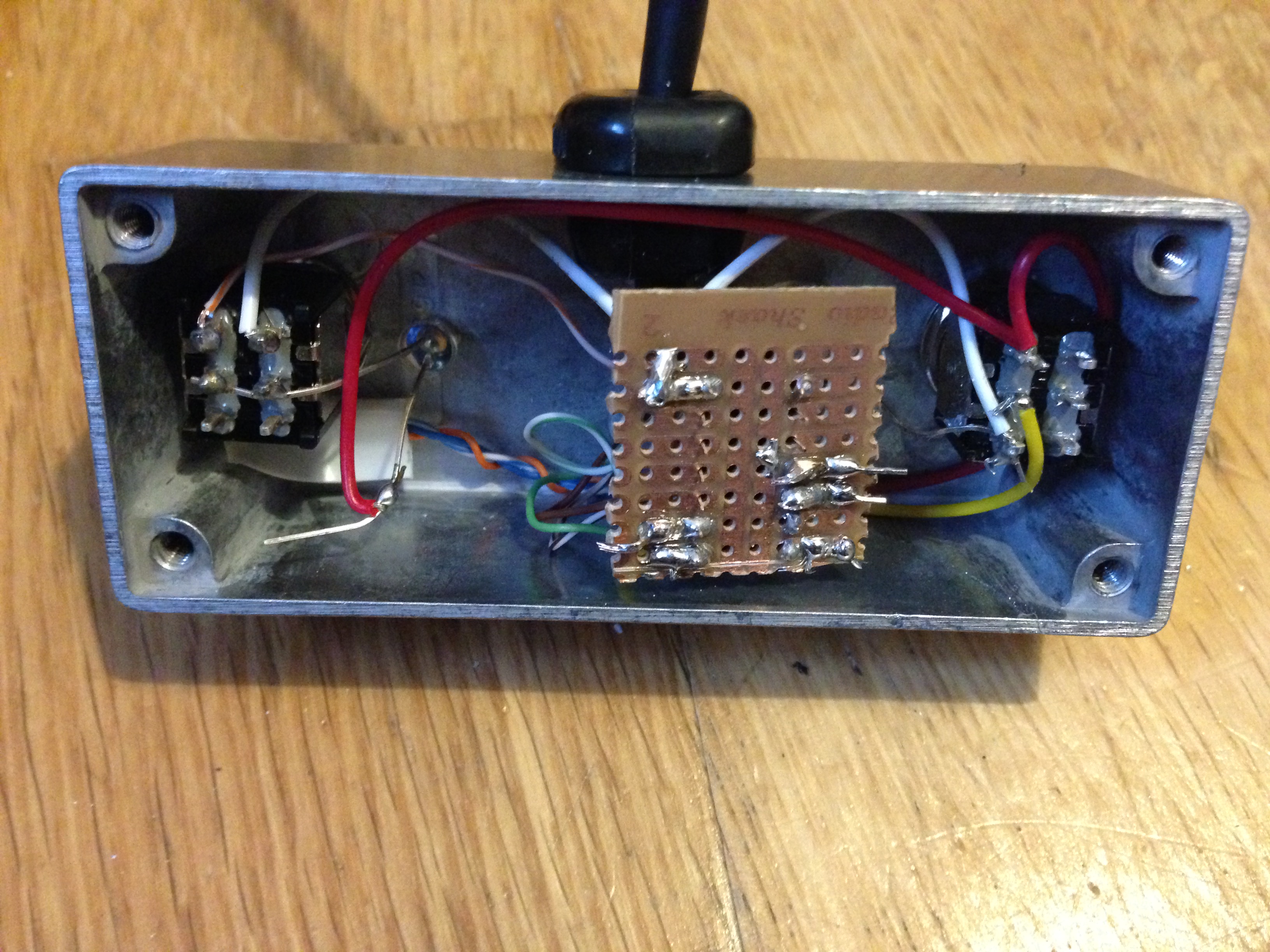
I’ve since built a new ExP that ads an expression output, but still fits in the mini enclousre below. I also managed to change the hardwired Cat-5 cable for a panel mount socket. See pictures below.
Links:
Neunaber Slate: http://neunaber.net/collections/pedals/products/slate-stereo-effect-pedal-v2
ExP Controller: http://neunaber.net/collections/pedals/products/exp
ExP Specification: https://docs.google.com/document/d/1dtP4e3Sp2izZ9LJ1SC9TPAYDjfYPpU8mbfK4Lh-GG54
4024 Datasheet:
https://media.digikey.com/pdf/Data%20Sheets/ST%20Microelectronics%20PDFS/HCF4024B.pdf
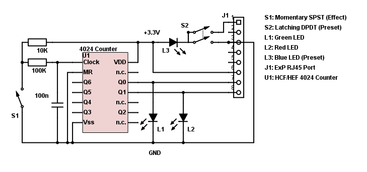
This is the most recent circuit I’ve used with has a switch bounce filter which allows the use of SPST soft touch footswitches:
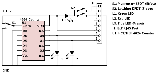
The first incarnation used a SPDT switch for the clock:
| Q1 | Q0 | Effect | LED |
|---|---|---|---|
| 0 | 0 | 4 | (off) |
| 0 | 1 | 3 | Green |
| 1 | 0 | 2 | Red |
| 1 | 1 | 1 | Orange |
Notes:
– Neunaber don’t cover warranty for custom ExP controllers, I can’t be held responsible if you break your pedal.
– While my pedal works, I’m not sure if I drew out the circuit exactly like I made it :P
– While I’ve used a counter so that I can cycle through the effects with a single momentary switch, the same could be achieved with 2 latching switches or a rotary encoder: http://www.fk-industrie.de/en/produktkatalog/P/D/E/A/27.html
– I’ve used an up counter which cycles the effects in reverse 4-3-2-1. Use a down counter if you want to go the right way.
– When the counter sets the effect inputs to high, it also turns on the LEDs.
– I used a two color LED for L1 and L2. Mine had a common cathode, some others you buy have a common anode and may need to be connected to the +3.3V rail, with the cathodes connected to Q0 and Q1.
– Power is provided through the ExP port, I’ve just labeled the rails for clarity.
– Since the supply is 3.3V, you need a HCF logic chip (Not HCT which is minimum 5V).
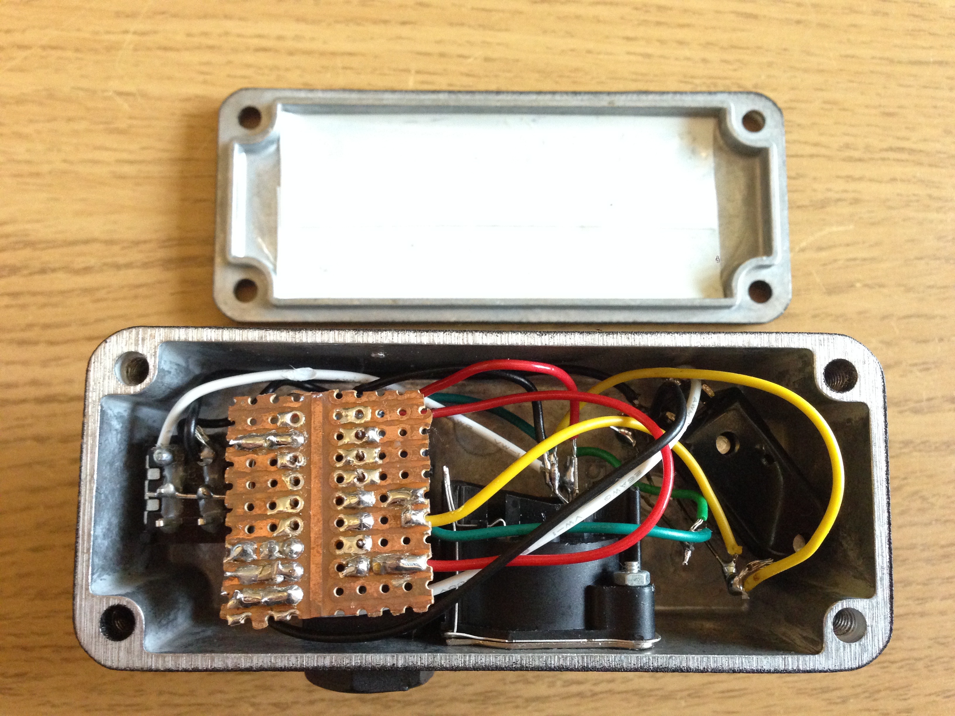
– I wired the RJ45 cable directly into the box to save space, but there are some nice panel mount sockets around.
– I’ve drawn a switches only circuit here: http://jameslow.com/2014/12/01/custom-neunaber-exp-3-switches/
Components:
Counter: http://www.maplin.co.uk/p/4024-cmos-logic-hcfhef-qx13p
2 Color LED: http://www.maplin.co.uk/p/5mm-multi-colour-led-yh75s
Panel Mount RJ45: http://www.gtcontact.com/Ethernet-RJ45-Plastic-Screw-Panel-DIP90.html


Hi
Your mod for Neunaber looks brilliant.
I am not very good at making these mods. SO do you by chance hae a modded Neunaber Slate for sale.
Kind regards
Bendt Aaen
Hmm, not sure, when you’re buying parts in low numbers the cost isn’t that much cheaper than an official one, I was just able to make it smaller. You can do it with just switches though, that would be easier, its just you only get 2 effects.
Ok Thanks.
I just thought that you were modifying the pedal itself…
Have a good one!
Kind regards
Bendt Aaen
Hey.
Happy to see that it’s quite possible to make this myself :-)
However, I wonder if you could explain in more detail, how the 4024 circuit actually works..?
I haven’t been able to find a simple explanation online :-(
I would like to see if I can find a way to use 4 leds so I’d have one colour for each effect.
Regards, and God bless.
Anders
Hi thanks for your comment!
The 4024 is basically just a digital counting chip. Every time the clock signal changes (Switch S1), the count goes up by 1. It actually counts from 0-63 and then when it gets to 63 goes back to 0.
For this circuit though we only uses outputs Q0 and Q1. By doing this we could, 0,1,2,3 then back to 0.
I think it’s possible to have different color LEDs for each effect by connect LEDs between pins 7 and 8, but you’d have to work it out, or might have to do it via a RGB LED, I think that’s how neunaber do it.
Thanks for you response!
I think what I dont fully understand are: what happens to the q1 and q2 legs of the chip?
Do they get connected to ground, or what happens?
Ah I see. Yes when the chip counts the outputs Q0, Q1, etc. count in binary. Binary 0 is ground, binary 1 is the high voltage, in this case 3.3V. Only outputs Q0 and Q1 are used in this circuit, this others are all left unattached.
In the ExP these are use to:
a) Drive inputs 7/8 of the RJ45 cable
b) Switch the LEDs on an off.
ah, now I understand.
Another question (tell me to stop if it’s too much :-)
Have you had trouble with the switching?
It seems the chip sometimes gets to a random effect, instead of the next in the “row”. I presume it has to do with the physical momentary switch having a minor gap between the two connections.
Would it be an idea to put a cap between the clock counter and ground, so it’s “held high” untill the switch latches to ground?
I haven’t had that issue at all, but someone else that tried my circuit commented on the YouTube video that they did. A capacitor might work, let me know if it does and I’ll pass it on to the other guy.
Been testing it out tonight. I used a tri color led, so that blue is always on, (connected directly to 3,3V) and the two other colors blend (from Q0 and Q1) to switch between blue, turquise, violet, and white.
I had to use some resistors to make the colors blend nicely (1k for blue, 3k3 for green, and red connected directly).
I ended up with a 22nF cap across pin 1 and 2 to help the switching become stable. I guess it’s a matter of whether the momentary switch has a small gap between it’s connections.
Anyways, thanks a bunch for your help!!
God Bless.
Can you explain exactly where you put the cap. Was it the common pin of the switch? Want to help someone else who has that problem.
Right now it’s still on the breadboard.
I used a clear tri-color led, and the light from it was a bit too directional – to the point where the light looked completely different, depending on the angle you view it from. I sanded it a bit, and it helped, so I’ve ordered a difused one instead, and am waiting for it, before I’m gonna solder the whole thing together.
I placed the cap from pin 1 to pin 2 on the chip, on the breadboard. probably I’ll try to posistion it as close to the chip as I can, because I think that’s where it helps the most.
Did that answer your quest? Otherwise ask again :)
So by pins 1 and 2 you mean between Clk and MR? Effectively Clk/S1 out and ground?
Yes.
From what I can tell, there can be a small gap in the switch between the two connections it switches between. The cap keeps the clock pin at 3,3v untill the switch connects it to ground.
Hello again.
I actually still had some trouble with the switching.
I think it’s finaly working as it’s supposed to now.
Here’s a link to the layout I ended up with:
https://www.dropbox.com/sh/4q1hasbg81dc9ig/AAAUBxXXRojbTpPHysuyiudAa?dl=0
You’re welcome to share it.
Regards
Anders
Thanks so much for the update!
Thanks for the info. I’m currently building one and will report back with some pictures when it’s done!
Couple of questions on anders’ layout if there is some way to contact him:
1. is the pin 2 connection supposed to be pin 1?
2. Are the dual and tri Color LEDs common anode or cathode, or does it not matter?
3.There is no connection shown on the layout for the third leg of the dual LED, does it just make a ground connection?
4. Are some of the resistors necessary in order for the controller to operate properly, or are they all just for controlling the brightness of the LEDs?
Hey.
1: You’re right – it should be pin 1 instead.
2-3: the tri-color led I use is common cathode.
The dual-color, actually only has two pins. This means that current can flow both ways in it – it just lights up with a different color, depending on which way the current flows. Here’s a link to where I bought it:
https://www.banzaimusic.com/LED-5mm-2-pin-red-green-Dual-Color.html
4: the 1K and 680R are for adjusting the brightness. The two 100R’s are neseccary to avoid pulling pin 1 below 3,3 volts.
Hope that helps :-)
Cool thanks a bunch
hello
ive seen your DIY EXP controller for Neunaber
that DIY fits on Stereo Wet Reverb? and how to store effects on it?
Chat conversation end
Just to answer Abby incase other people have the question too. Basically the ExP is just a switch that switches banks on the Neunaber Stereo v2 pedals. You switch banks using the ExP while the Neunaber is connected via USB to the computer and then use the pedal customizer software to update it: http://neunaber.net/pages/software
Hey James!
Thank you for all the detailed info you put here! Great job! Thanks to you I have already built a preset switch as a separate box, with only 6 bucks material costs. Now I’m thinking of building a second one just for the effect change. But after realizing that a bigger controller box would only fit on my pedalboard in a position quite far from the Neunaber pedal, I had an idea to add an effect on/off switch to the controller. Is it possible to achieve this through those 8 cat5 wires?
Thanks in advance!
Cheers,
Vlad
Hi Vlad. Really glad it helped you. I love what is possible with the Neunaber Expanse system. I don’t believe it’s possible to do an effect on and off over the CAT 5 cable though :(
Hi, James! I’m planning on building the ExP but I was wondering which schematic do you recommend: the one on the pdf file (2015) or the png image for the latest version (2016)?
If it is the latter, does that mean that there is no LED to indicate the preset? If there is a LED, does it still need the 100R resistors?
Hi, I’m not sure which pdf you’re talking about as my schematics both have LEDs. The LED isn’t essential to the functionality, it’s just useful to know which preset is active.