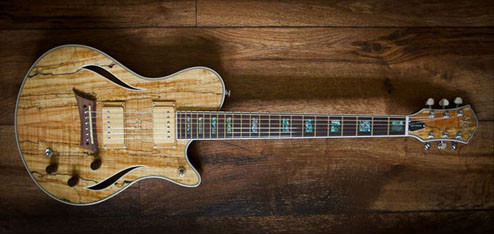
For a few years my main guitars has been a Michael Kelly Hybrid Special. These are fabulous looking guitars for the price, and an interesting setup with piezo bridge and electric pickups and stereo output. Being mid priced guitars though, there are some things that can be improved. Here is a list of what I’ve done to mine.
1. New pickups
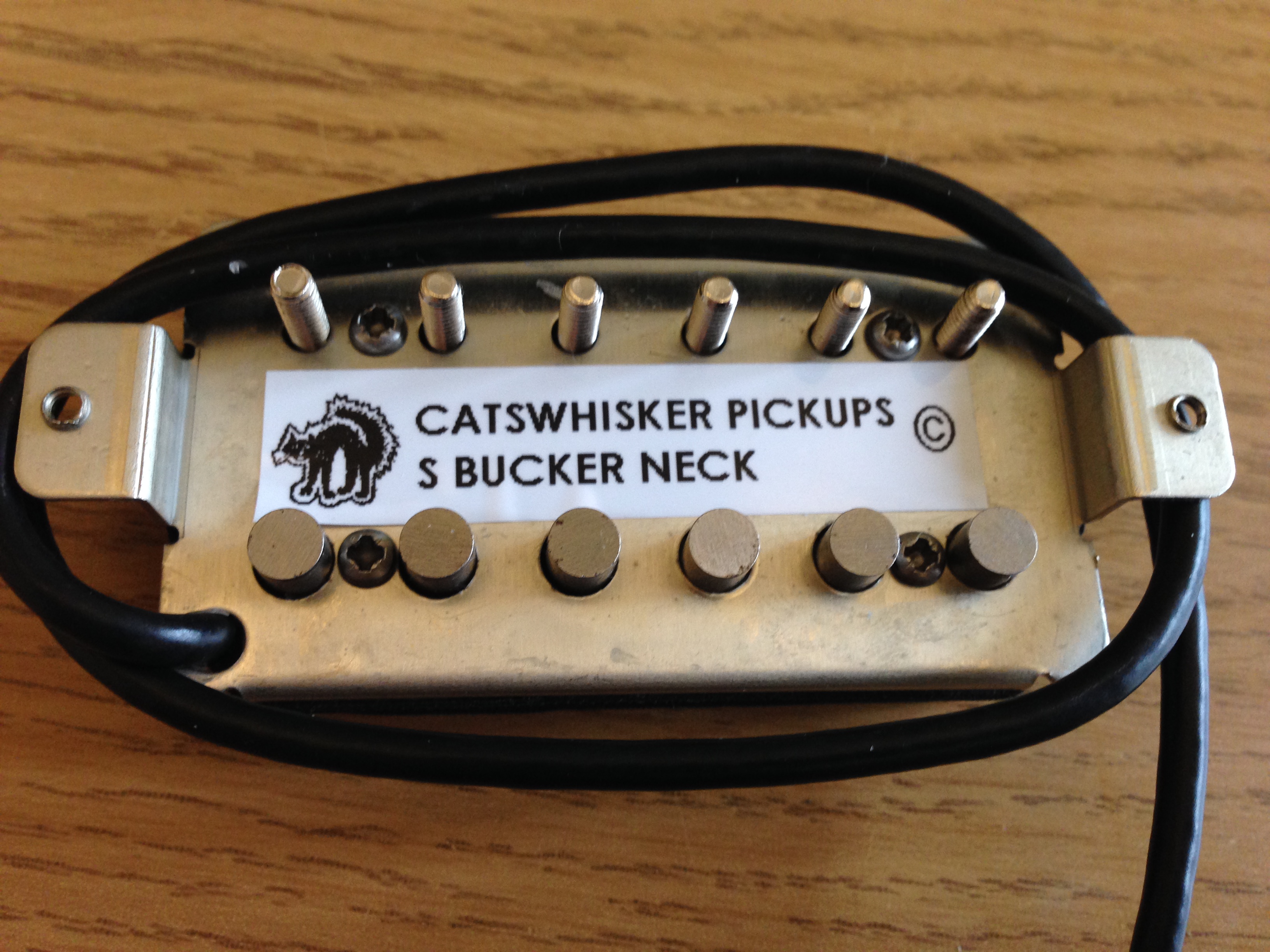
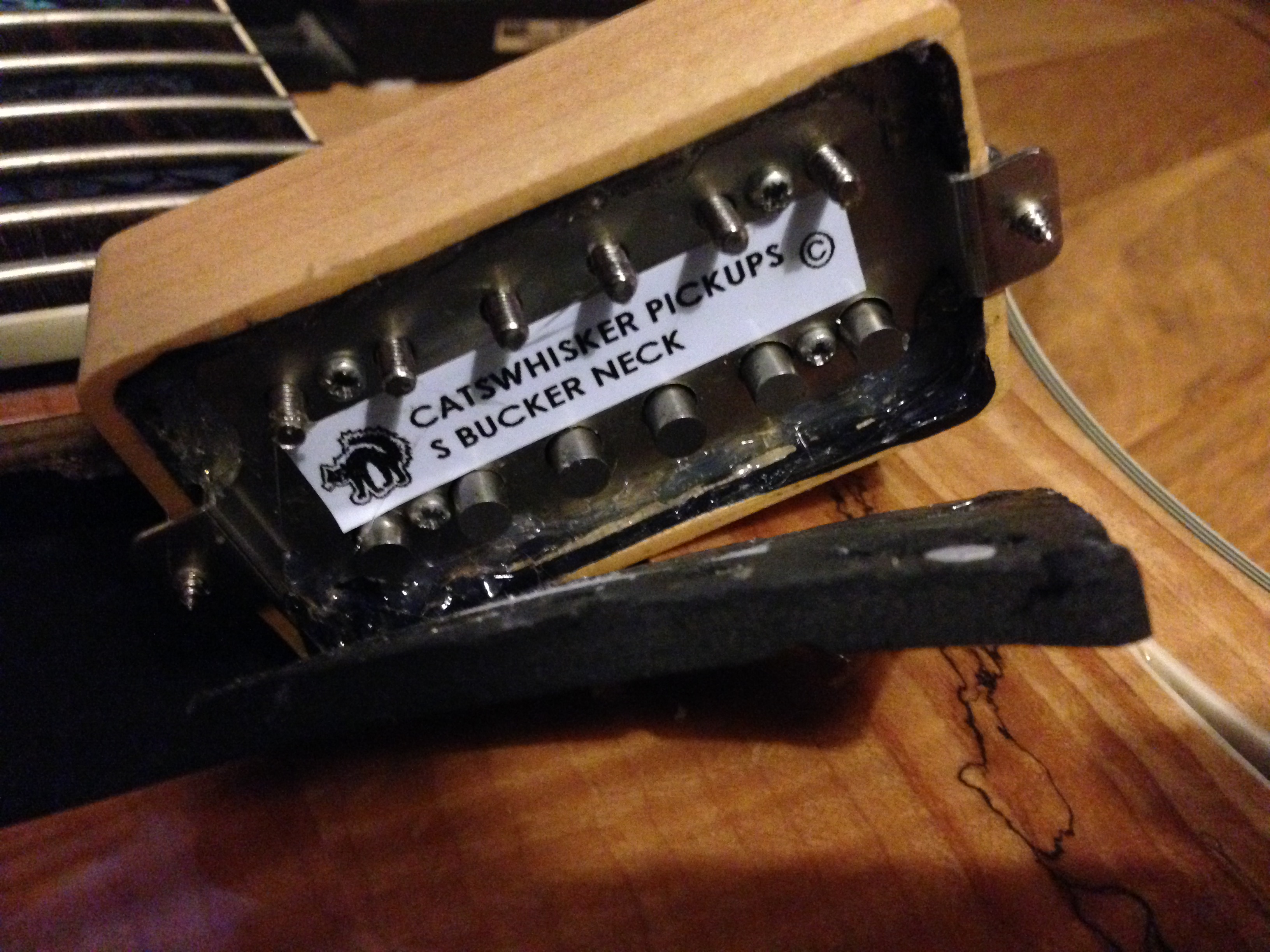
The stock rockfield pickups are ok, but a bit modern. I like a bassy and hotter bridge pickup, and more vintagy. I initially went for some Dimarzio Air Classics. The neck was ok, but the bridge was too weak. I changed the bridge to a Dimarzio AT-1 (similar to an Air Zone that I liked before), and the neck to a Catswhisker S-Bucker which has a better coil tap sound and classic/jazzy humbucker sound. I’m still not fully happy with the single coil sound so I may go for something else like a Lindy Fralin in the future.
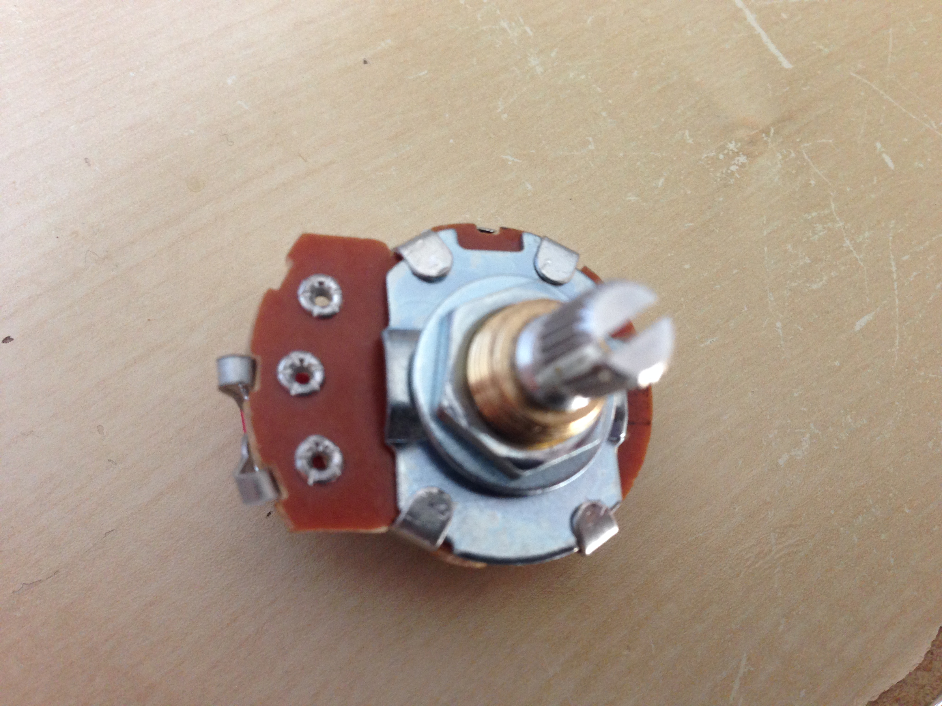
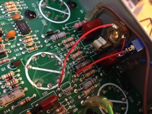
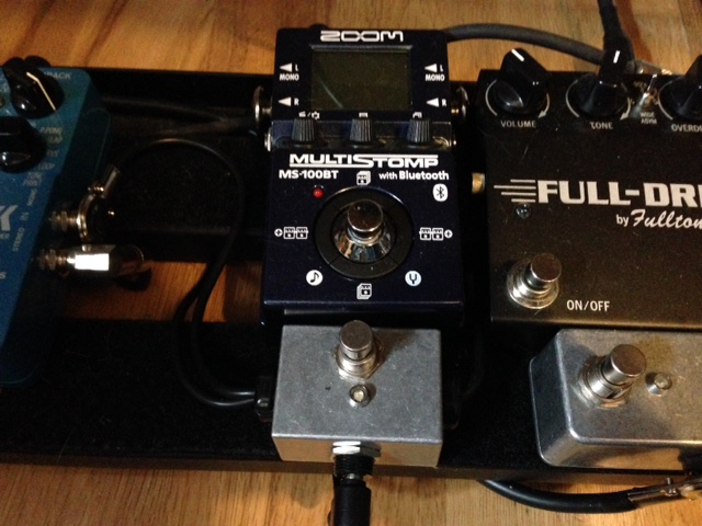
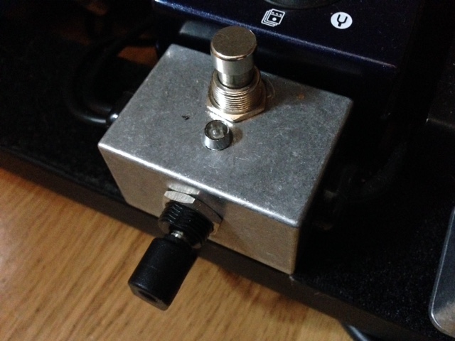
2. Volume pot replacement and coil tap switch
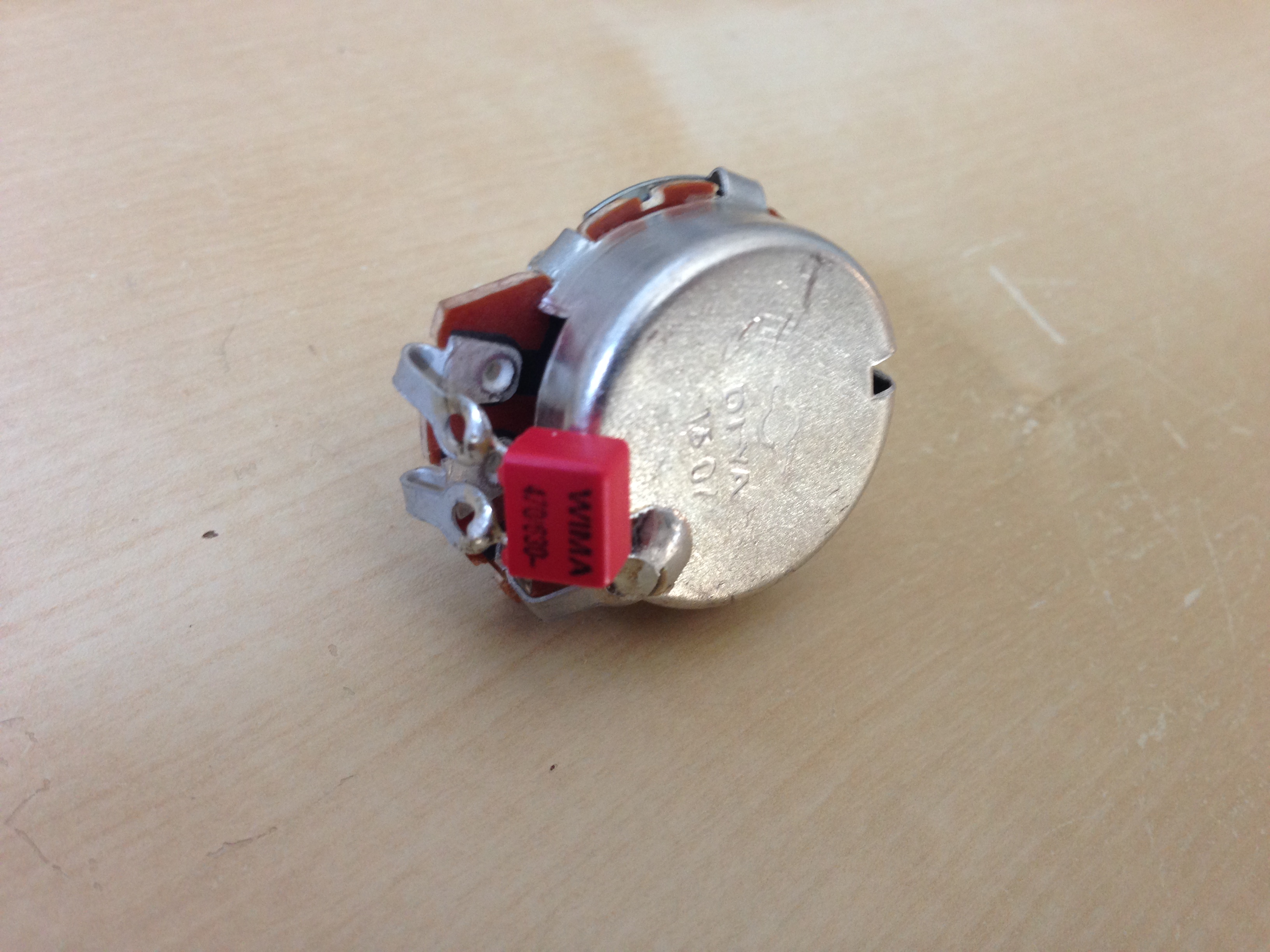
I found that the volume pot with the onboard switch got scratchy and loose very easily. I eventually changed it to a smooth Bournes full size pot, and installed a separate mini toggle coil tap switch. I think the original was a Bournes pot too, since it was really smooth, but having the switch on there too put too much wear on it. This also allowed me to install a 3PDT toggle switch and add a 470K resistor across the volume control when coil tapped. This makes the volume control a 250K pot, which really helped the single coil tone to be to bright and shrill.
3. Locking tuners
The grover tuners that come with it are great, but I wanted to lock down the tuning as much as possible. I bought some Grover 106C tuners, which stick up a little more than usual and so look different and change the tuning angle a little, but work great and make changing strings super fast.
4. Bone nut and saddle
Michael Kelly aren’t very specific about this on their website, but their customer service said “The nut is a synthetic graphite and the saddle is ABS”. Both my nut and saddle had started to wear in places, the strings didn’t sit properly in the nut, and I think was effecting tuning stability.
I bought a pre cut bone nut and saddle I found on eBay. I had to sand down the bottoms quite a bit, and the radius on the saddle was a bit flatter than the original, but close enough to work.
The tone of the electric side definitely improved. The fundamental note was louder, and upper harmonics a bit fuller. It didn’t sound significantly brighter, just fuller. Strangely I think the unplugged volume was a bit quieter, but that could just be my imagination. The bone nut helped the tuning stability a bit more.
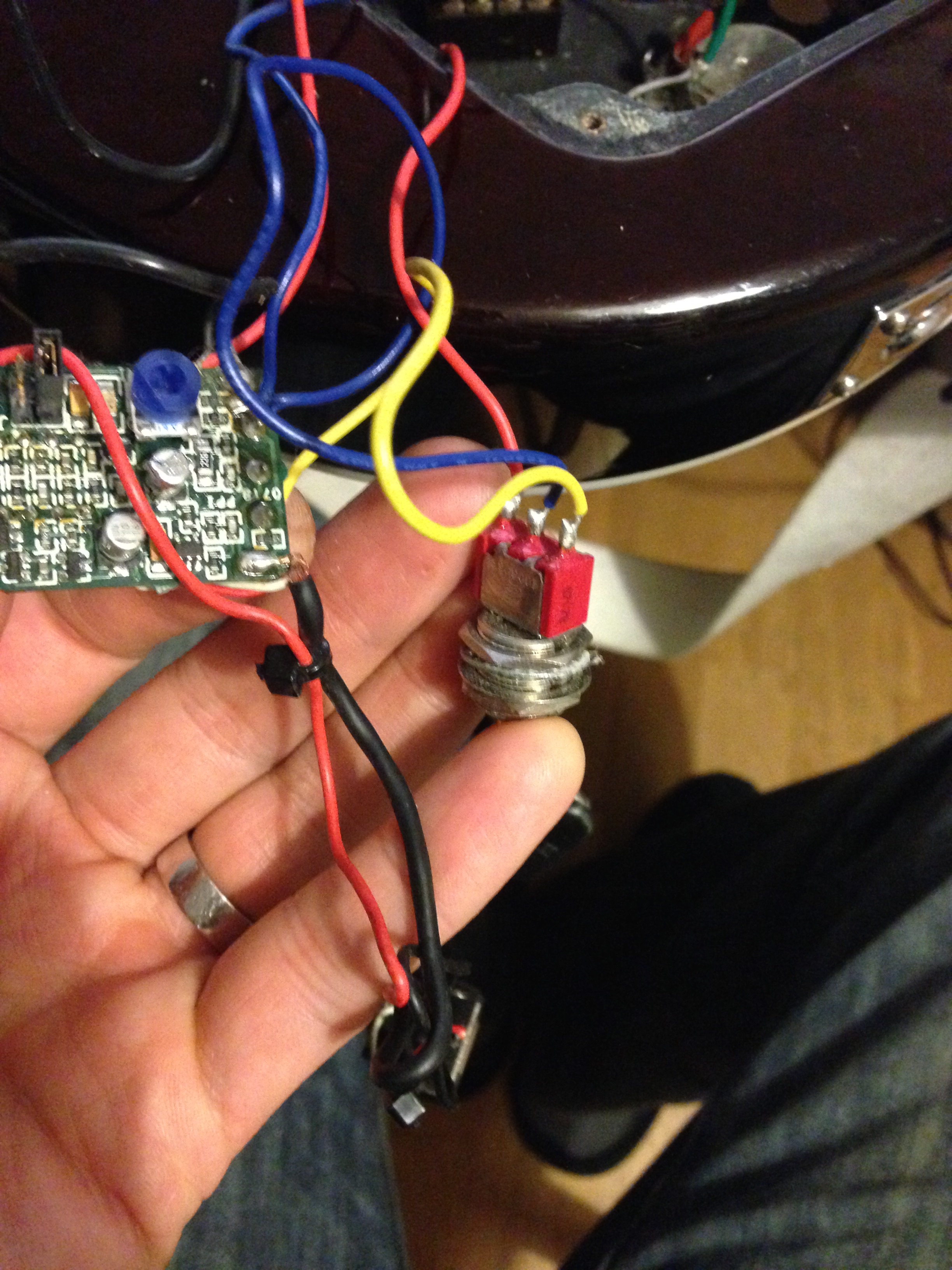
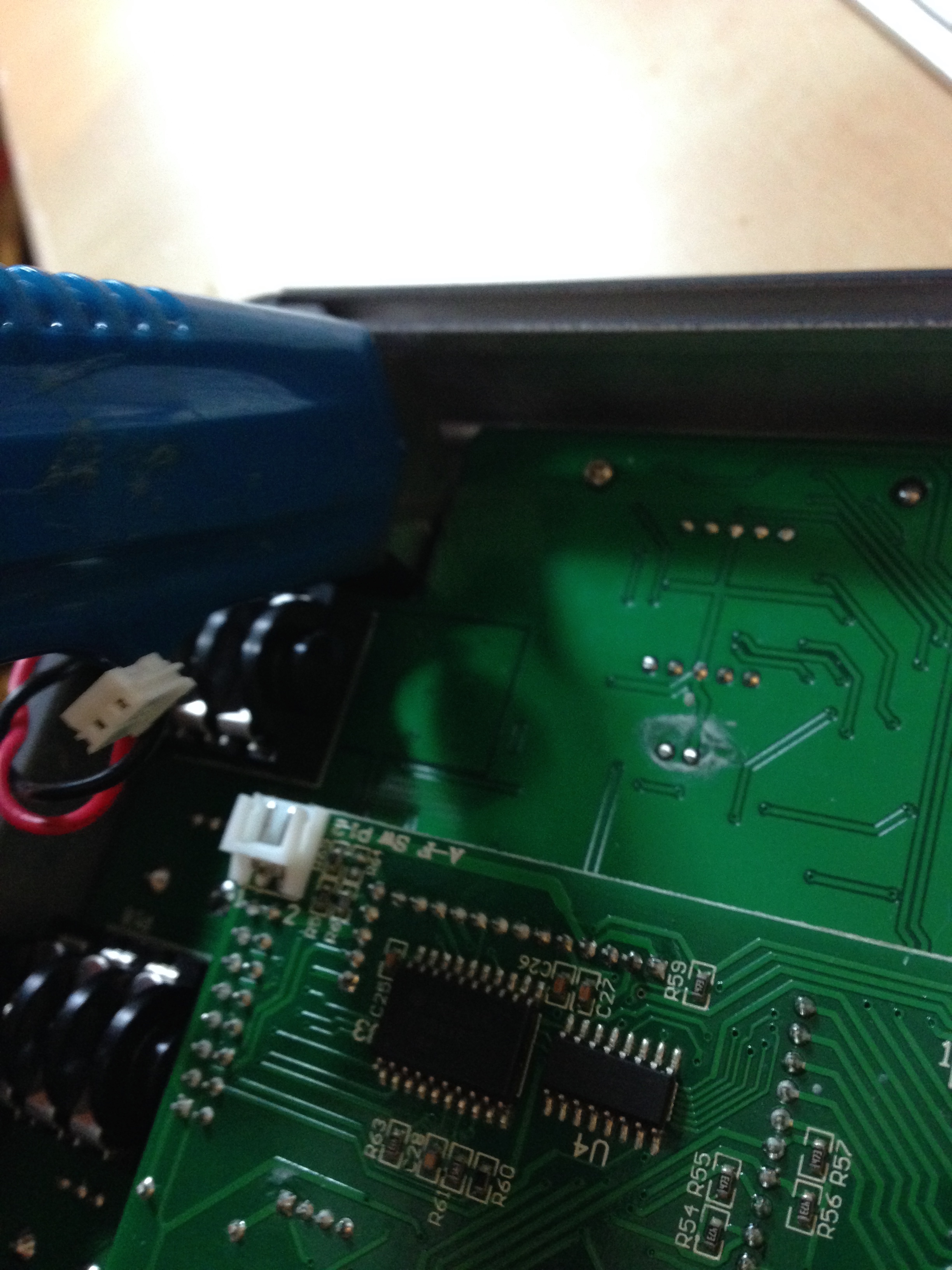
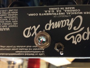
5. Removing active system
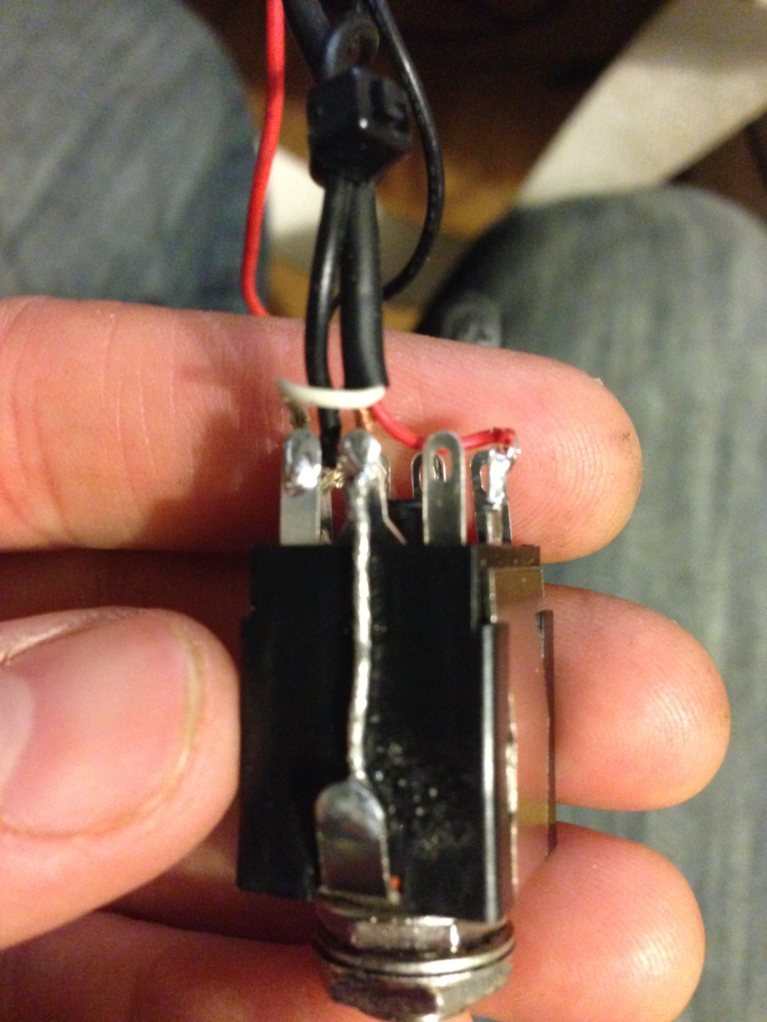
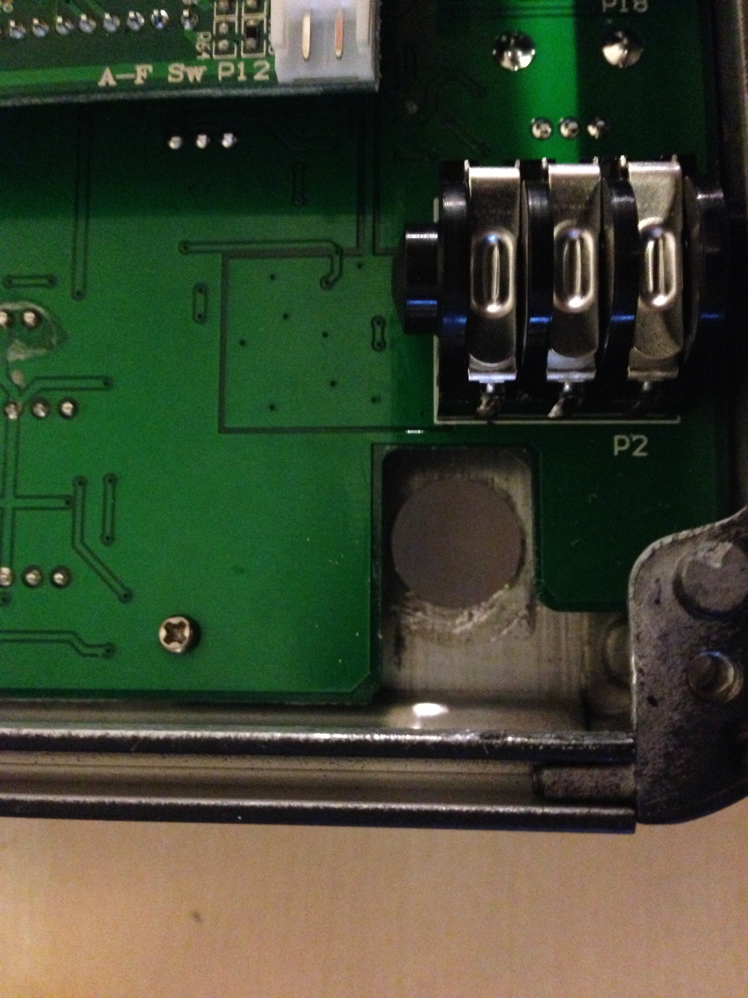
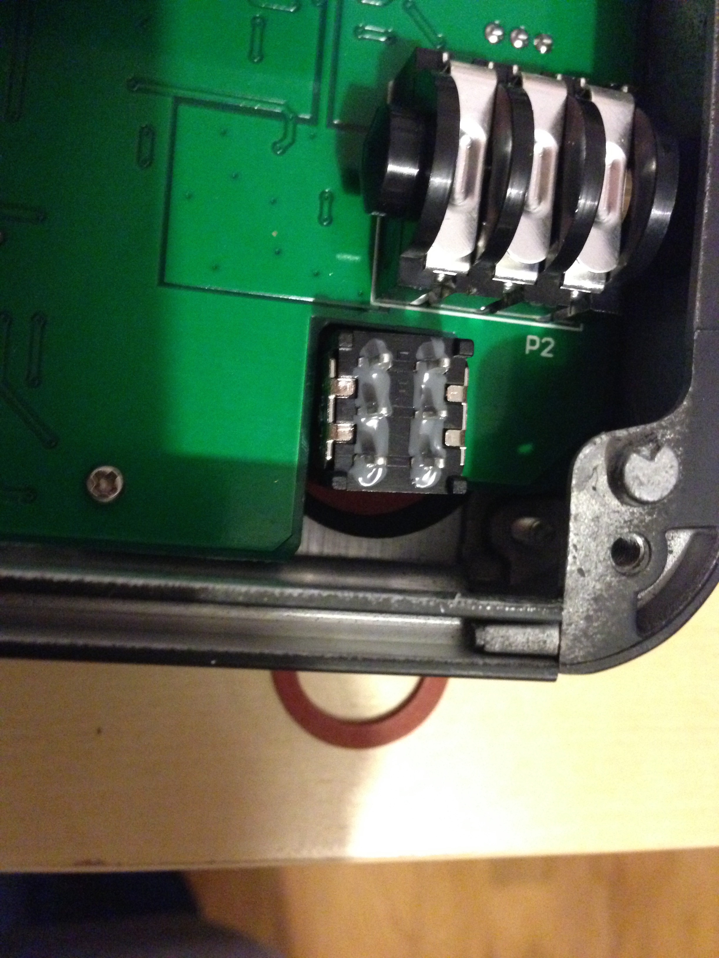
After a while I found the active system had two issues. Firstly the jack power switching was unreliable. This means that it would sometimes cut out or produce a large static noise if the jack was pulled at the wrong angle. Secondly the Fishman Powerbridge stereo cable detection was unreliable at detecting the stereo cable, so would sometimes send the piezo to the magnetic output by mistake, or do it only a little bit and produce a small hum.
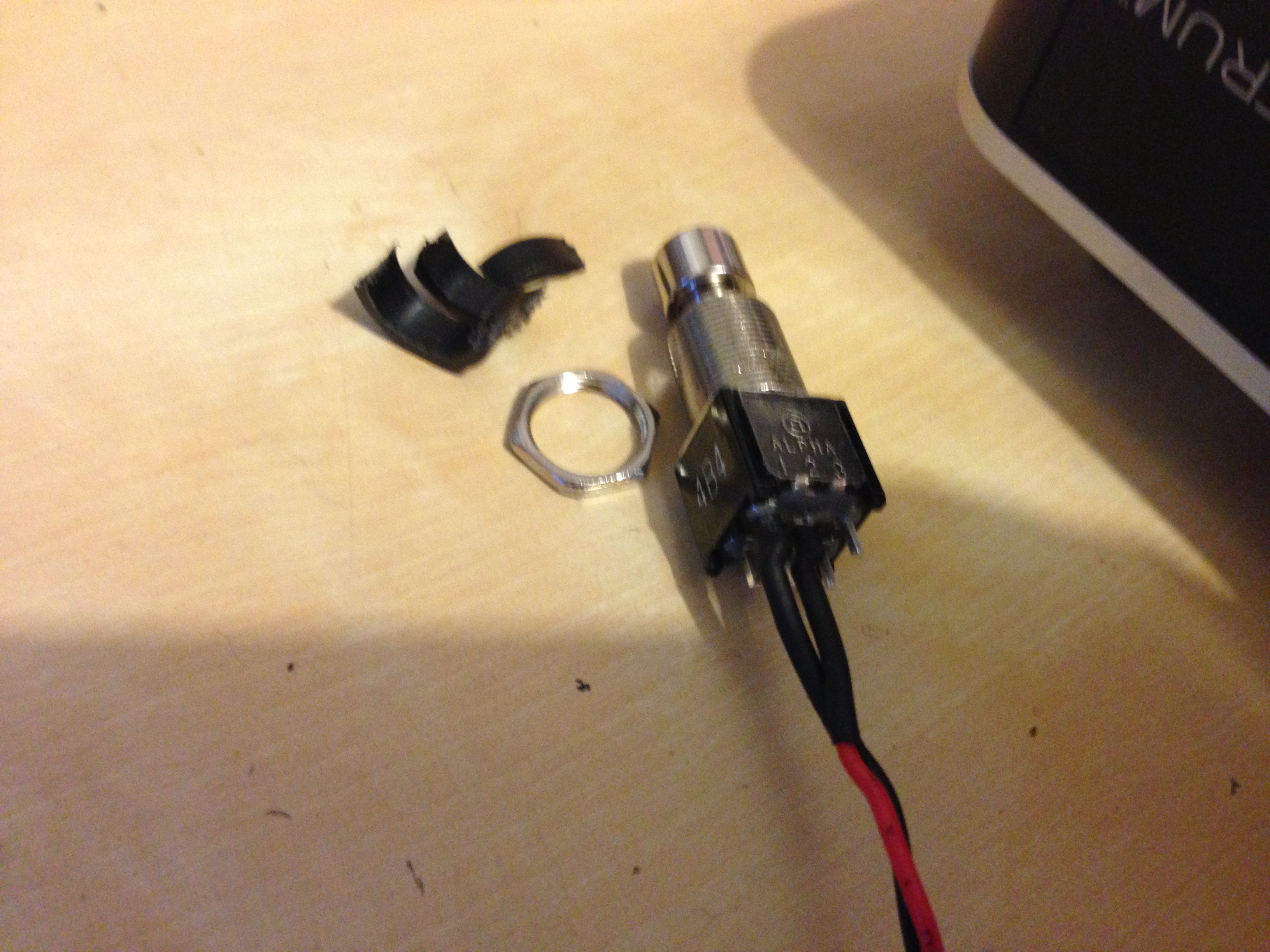
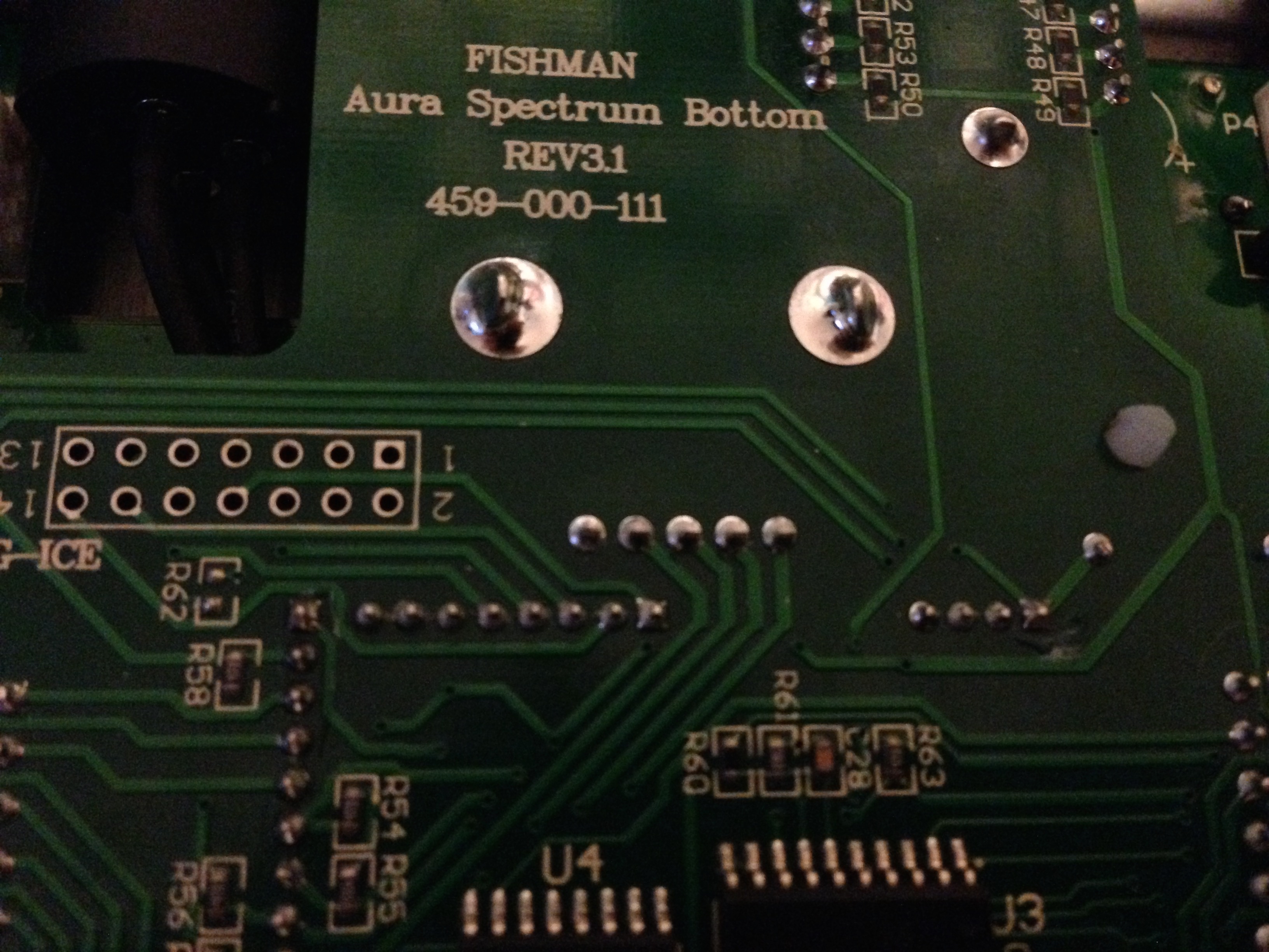
Eventually I decided it would be better to just go passive, install a 10 Meg volume pot with treble bleed and have a single switch for selecting stereo output, or sending the piezo to the mono output. In general it’s good to have a preamp as soon as you can in a piezo signal chain, but my Fishman Aura preamp pedal has a 10M input impedance, and I run short cables to that, so I thought overall it would be ok. The output volume from the piezo is definitely less, but the large pot and my preamp pedal’s high impedance mean it still seems to have a full bass response. I definitely prefer the solid metal switchcraft stereo socket, rather than the switching plastic type, and its good not to have to worry about running out of batteries.
Large value potentiometers don’t have a smooth taper, so Fishman actually recommend a different setup with multiple resistors and capacitors to use a smaller value pot while preserving bass response with the piezo. I might try that in the future, but for now the simple large 10M pot works.
http://www.fishman.com/files/powerbridge_install_guide.pdf
6. Future
There are two future mods I think I might do to the guitar to have it playing as well as possible.
– Refret and professional setup: The stock frets can’t be the hardest because I’ve already worn mine quite a bit, and have a little bit of buzzing. I might get it refretted with stainless steel so I never have to do it again.
– Change bridge to a hardtail steel piezo bridge. This would make it much easier to adjust the action and intonation of the guitar, but would be another job I need a professional to do, and I’m not sure how well they could refinish the place where the acoustic bridge is removed.